Bending is a process by which metal can be deformed by plastically deforming the material and changing its shape. The material is stressed beyond the yield strength but below the ultimate tensile strength. The surface area of the material does not change much. Bending usually refers to deformation about one axis.
Bending is a flexible process by which many different shapes can be produced. Standard die sets are used to produce a wide variety of shapes. The material is placed on the die, and positioned in place with stops and/or gages. It is held in place with hold-downs. The upper part of the press, the ram with the appropriately shaped punch descends and forms the v-shaped bend.
Bending is done using Press Brakes. Press Brakes normally have a capacity of 20 to 200 tons to accommodate stock from 1m to 4.5m (3 feet to 15 feet). Larger and smaller presses are used for specialized applications. Programmable back gages, and multiple die sets available currently can make for a very economical process.
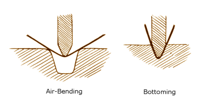
Air Bending is done with the punch touching the workpiece and the workpiece, not bottoming in the lower cavity. This is called air bending. As the punch is released, the workpiece ends up with less bend than that on the punch (greater included angle). This is called spring-back. The amount of spring back depends on the material, thickness, grain and temper. The spring back usually ranges from 5 to 10 degrees. Usually the same angle is used in both the punch and the die to minimize setup time. The inner radius of the bend is the same as the radius on the punch.

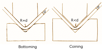
Bottoming or Coining is the bending process where the punch and the workpiece bottom on the die. This makes for a controlled angle with very little spring back. The tonnage required on this type of press is more than in air bending. The inner radius of the workpiece should be a minimum of 1 material thickness in the case of bottoming; and upto 0.75 material thickness, in the case of coining.

Design Considerations
The bend radius should be kept the same for all radiuses in the part to minimize set up changes. Bend radius guidelines are as follows:
•For most materials, the minimum inner radius should be at least 1 material thickness.
•As a general rule, bending perpendicular to rolling direction is easier than rolling parallel to the rolling direction. Bending parallel to the rolling direction can often lead to fracture in hard materials. Thus bending parallel to rolling direction is not recommended for cold rolled steel > Rb 70. And no bending is acceptable for cold rolled steel > Rb 85. Hot rolled steel can be bent parallel to the rolling direction.
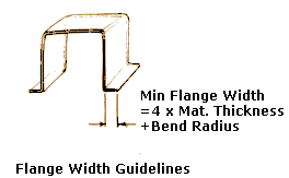
•The minimum flange width should be at least 4 times the stock thickness plus the bending radius. Violating this rule could cause distortions in the part or damage to tooling or operator due to slippage.

•Slots or holes too close to the bend can cause distortion of these holes. Holes or slots should be located a minimum of 3 stock thickness plus the bend radius. If it is necessary to have holes closer, then the hole or slot should de extended beyond the bend line.
•Dimensioning of the part should take into account the stack up of dimensions that can happen and mounting holes that can be made oblong should be.
•Parts should be inspected in a restrained position, so that the natural flexure of the parts does not affect measurements. Similarly inside dimensions in an inside bend should be measured close to the bend.

