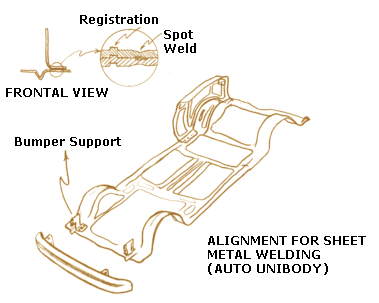
Welding is the process of permanently joining two or more metal parts, by melting both materials. The molten materials quickly cool, and the two metals are permanently bonded. Spot welding and seam welding are two very popular methods used for sheet metal parts.
Spot welding is primarily used for joining parts that normally upto 3 mm (0.125 in) thickness.
Spot-weld diameters range from 3 mm to 12.5 mm (0.125 to 0.5 in) in diameter.
Materials
•Low carbon steel is most suitable for spot welding. Higher carbon content or alloy steels tend to form hard welds that are brittle and could crack. This tendency can be reduced by tempering.
•Austenitic Stainless steels in the 300 series can be spot welded as also the Ferritic stainless steels. Martensitic stainless steels are not suitable since they are very hard.
•Aluminums can be welded using high power and very clean oxide free surfaces. Cleaning the surface to be oxide-free, adds extra costs (that can be avoided with low carbon steel).
•Dissimilar materials cannot be spot welded due to different melt properties and thermal conductivities. Plated steel welding takes on the characteristics of the coating. Nickel and chrome plated steels are relatively easy to spot weld, whereas aluminum, tin and zinc need special preparation inherent to the coating metals.
Manufacturing Considerations
•Thickness of the parts to be welded should be equal or the ratio of thicknesses should be less than 3:1.
•Spacing of welds
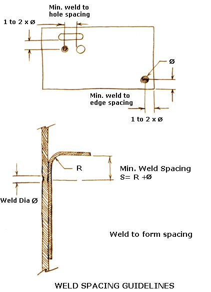
-Min. Weld to weld spacing = 10 x Stock thickness.
-Center of weld to edge distance = 2 x weld diameter, minimum.
-Weld to form distance = Bend Radius + 1 weld diameter, minimum.
•Adequate access for spot welding should be considered. Small flanges in U channels for example may restrict the electrode from entering the part.
•Flat surfaces are easier to spot weld due to easy access. Multiple bends impose access restrictions, and special fixtures may have to be designed to handle the parts, if access is not a problem.
•Prior to finishing, the spot welds have to be sanded or ground to blend the welds with the rest of the surface.
•It is best to choose the same spot weld size, to minimize setups and increase throughput.
•Plating of spot welded assemblies can cause problems when the sheet metal is overlapped. This can cause plating salts to be trapped-requiring special cleaning, or potential long-term corrosion problems. By carefully designing the assembly to allow easy draining of plating solutions this can be avoided.
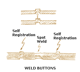
•The mating parts can be self-jigged for easy location prior to welding. This can be done by lancing one part and locating in a corresponding slot in the other part; or by boss type extrusion, weld buttons, in part locating to a slot in the other. This type of design can often eliminate the need for external fixtures.
Metal Inert Gas (MIG) Welding: An arc is struck between a consumable electrode and the sheet metal to be welded. The consumable electrode is in the form of continuous filler metal. An inert gas surrounds the arc and shields it from the ambient to prevent oxidation.
Carbon steels, low alloy steels, stainless steels, most aluminum alloys, zinc based copper alloys can be welded using this process.
Tungsten Inert Gas (TIG) Welding: An arc is truck between a tungsten electrode (non-consumable) and the sheet metal to be welded. An inert gas shields the arc from the ambient to prevent oxidation. A filler material is optional
Carbon steels, low alloy steels, stainless steels, most aluminum alloys, zinc based copper alloys can be welded using this process. TIG is quite suitable for welding dissimilar materials, but usual cautions of galvanic corrosion still apply.
The TIG process is a slower process compared to the MIG process, but the quality of weld is cosmetically better. There is no weld spatter, and the quality of welds is higher than MIG welding.
Oxy Acetylene Gas Welding: Acetylene or some combustible gas is combined with Oxygen and the flame heats the sheet metal to be welded. A filler metal rod supplies the molten metal for the joint.
This method is readily available, but the heat can cause distortion in sheet metal. Due to this, this method is being displaced by other methods such as MIG and TIG welding.
Types of Weld Joints
•Butt, T, corner, lap, and T joints are the common types of joints used in sheet metal welding. These can all be used with MIG and TIG welding.
•Corner joints are used frequently in sheet metal cabinet construction.
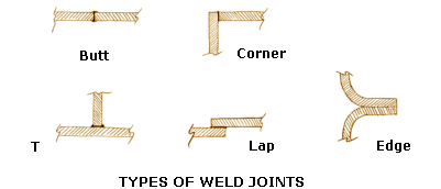
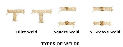
•Types of welds are often confused with the types of joints. The basic types of welds are fillet, square, and grooved.
Material Thickness and Weld Strength
•MIG welding can be done for thicknesses ranging from 0.5 mm to 6.3 mm (0.020 to 0.250 in). TIG can be used for thicknesses as low as 0.125 mm (0.005 in).
•Weld strength can be upto the strength of the underlying material. To improve overall system robustness it is better to increase material thickness rather than over specifying the weld.
Manufacturing Considerations
•The surface to be welded needs to be clean and degreased and any foreign debris should be removed. In the case of hot-rolled steel or aluminum, wire brushing may need to be done to remove scales and oxides, for the highest quality welds.
•Weld distortion occurs whenever a weld is done. This can be minimized by spacing the weld tacks at least 50 mm (2 in) apart. Welding distortion can also be minimized by fixturing (and clamping) while welding as well as heat sinking.
•Parts should be designed with features that are self-locating with respect to mating parts. This removes the need for dedicated fixtures and its costs. Fixtures also introduce additional tolerances due to deflections imposed on the parts by the clamping pressure. Fixtures can also slow down production due to fact that parts have to be placed in the fixture and clamps (if any) that need to be activated.
•Welds locations should be located with operator access in mind. If it is not accessible to a weld electrode, it is not weldable. Thus, in designs that involve sections such as channels, boxes access of electrodes needs to be considered.
•Tolerancing of welded parts is usually generous. This allows the parts to be welded without too much elaborate fixturing or secondary processing such as grinding. If tight tolerancing is desired, it is best achieved by self-locating features on the mating parts.
Cosmetics Considerations
•MIG welding causes a lot of spatter that needs to be sanded or filed, if cosmetically objectionable. Thus, it is best to avoid MIG welding on exterior surfaces if cosmetics are important. TIG welding is better suited for no spatter welding, even though it is more expensive.
•The parts that are to be welded need to fit well with each other without too large a gap. This is particularly important in fusion welding, where no filler material is used. If too large a gap is used, then excessive shrinkage will take place.
Finish Considerations
•Parts that need painting will require surface preparation in the form of sanding and grinding. The cost of this preparation needs to be considered in the total cost.
•Parts that need to be electroplated should have seams that do not overlap, and not have corners or edges where the plating solutions can be trapped, leading to corrosion in the long term.
Projection welding is a variation of spot welding. Projections are designed in one part. These act as current concentrators for the welding process. When the two parts are mated together, these projections are the high points that first make contact. As the power is cycled, the projections simultaneously carry the current and are welded. This process is known as Resistance Projection Welding, RPW.
Due to the efficiency of power transfer, thicker materials can be successfully welded. Materials as thick as 3 mm (0.125 in) can be successfully welded. For thin stock, the traditional spot welding is a preferred method.
Low carbon steels, low alloy steels, stainless steels, as well as aluminum can be welded using this process.
Projections are usually semi-spherical or blunt conical type.
Projection welding requires that the height of projections be controlled to within a range of 0.075 mm (0.003 in).
